
Technical description
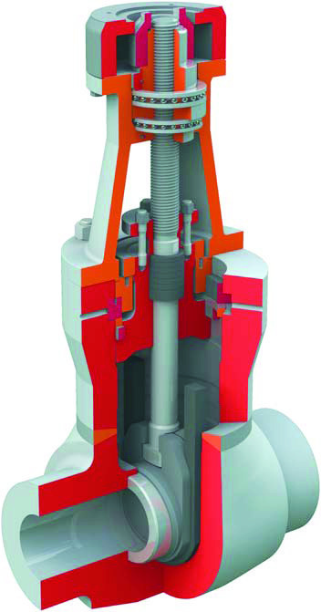
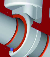
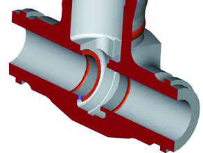
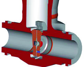
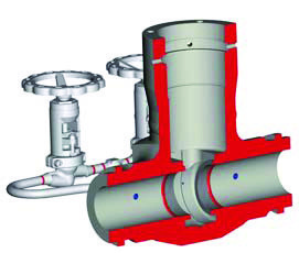
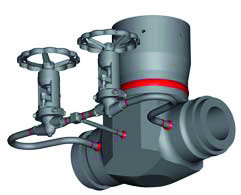
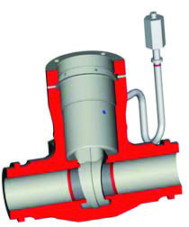
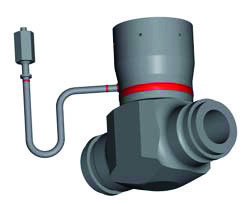
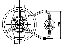
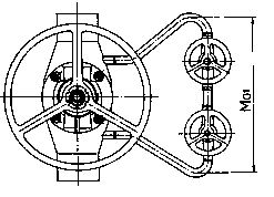
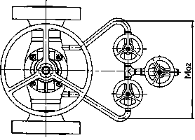
Body made of closed-die or open-die forging, cast or welded yoke. Seats pressed into the body and secured with a seal weld. Sealing surfaces of the seats and wedge hard-faced with a hard-facing alloy. Stem packing and pressure seal bonnet sealing ring are made of expanded graphite. The gate valves are designed for full differential pressure and no bypass is required. If a bypass is required, they are supplied with one to three valves and a T-piece for a piping bypass. They can also be equipped with protection of the central part of the body. The design of S43 gate valves includes sizing of the main parts according to the pressure-temperature system. On request, a packing permanently loaded by a spring (Live Loading System) can be supplied. This design is used where operating conditions do not allow frequent inspection of the valve or the nature of operation rules out regular maintenance of the packing.
Image gallery
Drawings and dimensions
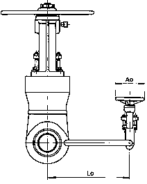
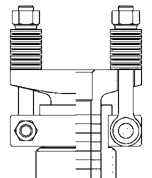
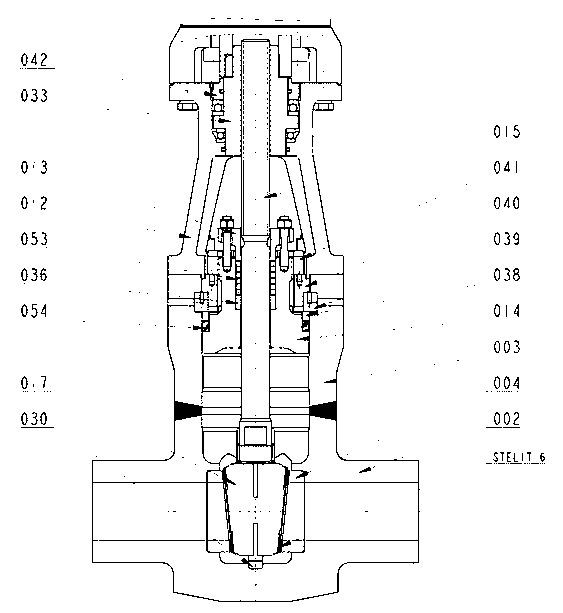
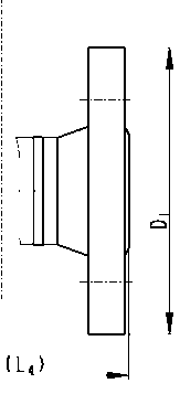
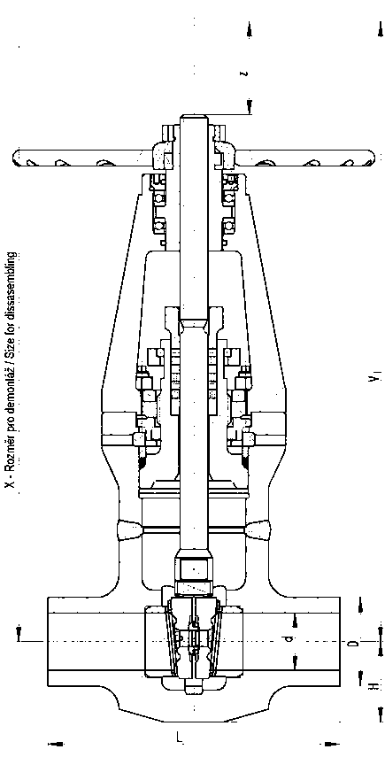
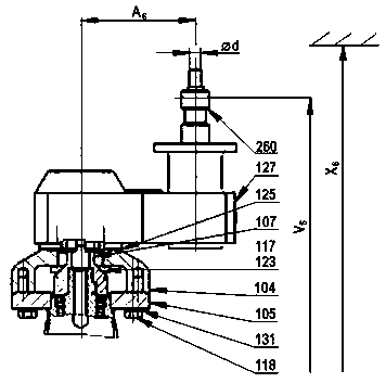
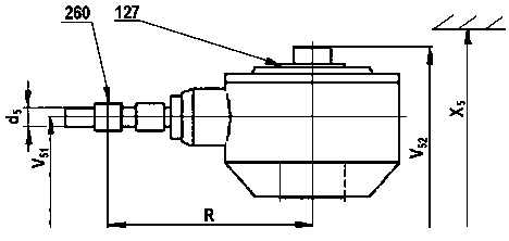
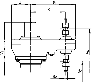
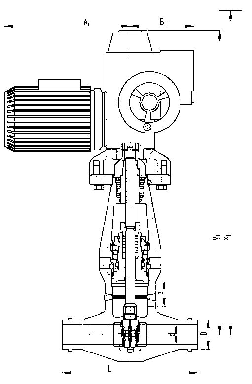
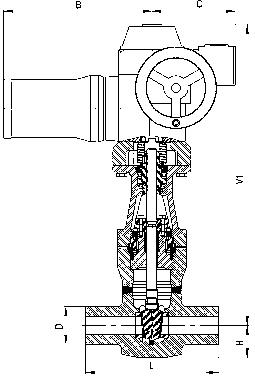
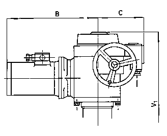
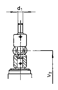
Application
Shut-off valve for water, steam and other media used in power and chemical plants, depending on the choice of body material, for normal, tropical, explosive and seismic environments.
Operation
Operated by handwheel, electric actuator (also for seismic requirements), spur or bevel gear and by direct remote control. Gate valves with a handwheel can be equipped with a locking device.
Testing
The gate valves are tested with water (or steam at the customer's request) for strength, body tightness, operability and seat tightness depending on the operating parameters and body material. The minimum test pressure for the strength test is 1.5 times PN. Pressure-bearing welds are radiographed.
Installation
The gate valves can be installed in any position regardless of the flow direction of the working medium. It is recommended to install larger gate valves in horizontal piping with the stem vertical and the actuator on top.
Dimensions
| DN/d | PN | Dk* | V I | X | d,D,D 1 | H | Z | L EN 4 | L ČSN 4 | kg | L EN | L ČSN | kg |
|---|---|---|---|---|---|---|---|---|---|---|---|---|---|
| 65/50 65/55 | 63,100 | 320 | 535 | 1310 | 70 | 75 | 290 | 340 | 71 | 290 | 360 | 58 | |
| 160 | 360 | 360 | 75 | 360 | |||||||||
| 250 | 425 | 425 | 78 | ||||||||||
| 80/75 | 63,100 | 400 | 710 | 1560 | 91 | 100 | 310 | 360 | 110 | 310 | 450 | 95 | |
| 160 | 390 | 390 | 115 | 450 | |||||||||
| 250 | 470 | 470 | 123 | ||||||||||
| 100/75 | 63,100 | 400 | 710 | 1560 | 91 | 100 | 350 | 400 | 118 | 350 | 450 | 96 | |
| 160 | 450 | 450 | 125 | 450 | |||||||||
| 250 | 550 | 650 | 135 | ||||||||||
| 125/110 | 63,100 | 500 | 920 | 1820 | 127 | 140 | 400 | 450 | 270 | 400 | 550 | 233 | |
| 160 | 525 | 625 | 280 | 550 | |||||||||
| 250 | 650 | 650 | 292 | ||||||||||
| 150/110 | 63,100 | 500 | 920 | 1820 | 127 | 140 | 450 | 500 | 278 | 450 | 550 | 230 | |
| 160 | 600 | 600 | 297 | 550 | |||||||||
| 250 | 750 | 750 | 315 | ||||||||||
| 175/125 | 63,100 | 630 | 1105 | 2105 | 155 | 165 | - | - | - | 550 | 650 | 435 | |
| 160 | - | - | 650 | ||||||||||
| 250 | - | - | |||||||||||
| 175/150 200/150 | 63,100 | 630 | 1120 | 2120 | 155 | 180 | 550 | 600 | 503 | 550 | 650 | 425 | |
| 160 | 750 | 750 | 542 | 650 | |||||||||
| 250 | 950 | 950 | 572 | ||||||||||
| 225/175 | 63,100 | 710 | 1390 | 2540 | 186 | 220 | - | - | - | 650 | 700 | 718 | |
| 160 | - | - | 700 | ||||||||||
| 250 | - | - | |||||||||||
| 250/200 | 63,100 | 710 | 1455 | 2855 | 205 | 240 | 650 | 700 | 956 | 650 | 800 | 831 | |
| 160 | 900 | 900 | 1025 | 800 | |||||||||
| 250 | 1150 | 1150 | 1079 | ||||||||||
| 275/200 | 63,100 | 710 | 1455 | 2855 | 205 | 240 | - | - | - | 750 | 850 | 837 | |
| 160 | - | - | 850 | ||||||||||
| 250 | - | - | |||||||||||
| 250/225 | 63,100 | 800 | 1619 | 3120 | 235 | 260 | - | - | - | 650 | 800 | 1020 | |
| 160 | - | - | 800 | ||||||||||
| 250 | - | - | |||||||||||
| 275/225 300/225 | 63,100 | 800 | 1619 | 3120 | 235 | 260 | 750 | 800 | 1183 | 750 | 900 | 1020 | |
| 160 | 1050 | 1050 | - | 900 | |||||||||
| 250 | - | - | - | ||||||||||
| 300/250 | 63,100 | - | - | - | 210 | 290 | 750 | 800 | - | 750 | 1000 | - | |
| 160 | 1050 | 1050 | - | 1000 | |||||||||
| 250 | - | ||||||||||||
| 350/275 | 63,100 | - | - | - | 285 | 310 | - | - | - | 850 | 1000 | - | |
| 160 | - | - | 1000 | ||||||||||
| 250 | - | - | - | - | |||||||||
| 400/275 | 63,100 | - | - | - | 285 | 310 | - | - | - | 950 | 1000 | - | |
| 160 | - | - | - | 1000 | |||||||||
| 250 | - | - | - | - |
| DN | PN | Bevel gear – S43 1x6 | Spur gear – S43 1x2 | |||||||||||
|---|---|---|---|---|---|---|---|---|---|---|---|---|---|---|
| S43 1x6 | S43 1x2 | |||||||||||||
| type | R | d 5 | V 51 | V 52 | X 5 | kg | type | A 6 | Ød | V 6 | X 6 | kg | ||
| 65/50 65/55 | 63,100 | GK14.2 | 174 | 20 | 580 | 668 | 1500 | 74,5 | GST14.1 | 240 | 18/29 | 716 | 1550 | 88 |
| 160 | ||||||||||||||
| 250 | ||||||||||||||
| 80/75 100/75 | 63,100 | GK14.2 | 174 | 20 | 719 | 807 | 1800 | 121 | GST14.1 | 240 | 18/29 | 855 | 1850 | 133 |
| 160 | ||||||||||||||
| 250 | ||||||||||||||
| 125/110 150/110 | 63,100 | GK14.2 | 174 | 20 | 902 | 990 | 2000 | 257 | GST14.1 | 240 | 18/29 | 1038 | 2050 | 269 |
| 160 | ||||||||||||||
| 250 | GK16.2 | 234 | 30 | 915 | 1004 | 2000 | 268 | GST16.1 | 300 | 18/29 | 1063 | 2060 | 283 | |
| 175/125 | 63,100 | GK16.2 | 234 | 30 | 1027 | 1116 | 2200 | 467 | GST16.1 | 300 | 18/29 | 1175 | 2260 | 481 |
| 160 | ||||||||||||||
| 250 | ||||||||||||||
| 175/150 200/150 | 63,100 | GK16.2 | 234 | 30 | 1063 | 1152 | 2200 | 456 | GST16.1 | 300 | 18/29 | 1211 | 2260 | 471 |
| 160 | ||||||||||||||
| 250 | GK25.2 | 306 | 30 | 1078 | 1184 | 2200 | 491 | GST25.1 | 360 | 29/35,5 | 1293 | 2300 | 517 | |
| 225/175 | 63,100 | GK16.2 | 234 | 30 | 1248 | 1437 | 2600 | 776 | GST16.1 | 300 | 18/29 | 1396 | 2600 | 791 |
| 160 | GK25.2 | 306 | 30 | 1263 | 1469 | 2700 | 811 | GST25.1 | 360 | 29/35,5 | 1478 | 2750 | 837 | |
| 250 | ||||||||||||||
| 250/200 275/200 | 63,100 | GK16.2 | 234 | 30 | 1348 | 1537 | 2800 | 863 | GST16.1 | 300 | 18/29 | 1496 | 2800 | 1064 |
| 160 | GK25.2 | 306 | 30 | 1363 | 1569 | 2830 | 907 | GST25.1 | 360 | 29/35,5 | 1578 | 2850 | 1146 | |
| 250 | ||||||||||||||
| 250/225 275/225 300/225 | 63,100 | GK25.2 | 306 | 30 | 1487 | 1693 | 3020 | 1073 | GST25.1 | 360 | 29/35,5 | 1702 | 3050 | 1323 |
| 160 | GK30.2 | 528 | 40 | 1544 | 1754 | 3060 | 1141 | GST30.1 | 380 | 29/35,5 | 1707 | 3050 | 1328 | |
| 250 | ||||||||||||||
| 300/250 | 63,100 | GK25.2 | 306 | 30 | 1648 | 1854 | 3160 | 1528 | GST30.1 | 380 | 29/35,5 | 1863 | 3200 | 1767 |
| 160 | ||||||||||||||
| 250 | GK30.2 | 528 | 40 | 1703 | 1893 | 3200 | 1578 | |||||||
| 350/275 400/275 | 63,100 | GK25.2 | 306 | 30 | 1920 | 2126 | 3676 | 2940 | GST30.1 | 380 | 29/35,5 | 2135 | 3500 | 2993 |
| 160 | GK30.2 | 528 | 40 | 1975 | 2165 | 3715 | 2898 | |||||||
| 250 | ||||||||||||||
| Pos. | Part identification | Material – standard |
|---|---|---|
| 260 | Shaft joint | ON 13 3123 |
| 131 | Washer | ČSN 02 1741.10 |
| 127 | Transmission | AUMA GST / GK |
| 125 | Insulating ring | TEMAPLUS |
| 123 | Washer | ČSN 02 1740.10 |
| 118 | Screw | ČSN EN ISO 4017 |
| 117 | Screw | ČSN EN ISO 4762 |
| 107 | Connector | C 35 |
| 105 | Flange | P 285NH |
| 104 | Bridge | GC-17CrMo55-P 285NH |
| DN | PN | MODACT MON | |||||
|---|---|---|---|---|---|---|---|
| motor | A 1 | B 1 | V 1 | X 1 | kg | ||
| 65/50 65/55 | 63,100 | 52031 | 436 | 228 | 808 | 1590 | 100 |
| 160 | |||||||
| 250 | |||||||
| 80/75 100/75 | 63,100 | 52031 | 436 | 228 | 947 | 1800 | 145 |
| 160 | |||||||
| 250 | |||||||
| 125/110 150/110 | 63,100 | 52032 | 436 | 228 | 1130 | 2030 | 285 |
| 160 | |||||||
| 250 | 52033 | 519 | 258 | 1187 | 2090 | 337 | |
| 175/125 | 63,100 | 52033 | 519 | 258 | 1299 | 2300 | 529 |
| 160 | |||||||
| 250 | 52034 | 519 | 258 | 1299 | 2300 | 536 | |
| 175/150 200/150 | 63,100 | 52033 | 519 | 258 | 1355 | 2360 | 522 |
| 160 | 52034 | 519 | 258 | 1355 | 2360 | 526 | |
| 250 | 52035 | 598 | 298 | 1395 | 2400 | 535 | |
| 225/175 | 63,100 | 52033 | 519 | 258 | 1520 | 2670 | 842 |
| 160 | 52035 | 598 | 298 | 1580 | 2730 | 969 | |
| 250 | |||||||
| 250/200 275/200 | 63,100 | 52034 | 519 | 258 | 1622 | 2890 | 932 |
| 160 | 52035 | 598 | 298 | 1680 | 2940 | 1055 | |
| 250 | |||||||
| 250/225 275/225 300/225 | 63,100 | 52035 | 598 | 298 | 1804 | 3130 | 1221 |
| 160 | 52036 | 665 | 298 | 2071 | 3400 | 1329 | |
| 250 | 52036 | 665 | 298 | 2071 | 3400 | ||
| 300/250 | 63,100 | 52036 | 665 | 298 | 2225 | 3625 | 1970 |
| 160 | |||||||
| 250 | - | - | - | - | - | - | |
| 350/275 400/275 | 63,100 | - | - | - | - | - | - |
| 160 | - | - | - | - | - | - | |
| 250 |
| DN/d | PN | B | C | D | H | L | V1 | 123P |
|---|---|---|---|---|---|---|---|---|
| kg | ||||||||
| 65/50 | 320 ÷ 400 | 420 | 230 | 122 | 85 | 360 | 815 | 150 |
| 65/55 | 150 | |||||||
| 80/55 | 150 | |||||||
| 100/55 | 150 | |||||||
| 80/75 | 195 | 450 | 160 | 125 | 450 | 1240 | 335 | |
| 100/75 | 340 | |||||||
| 100/80 | 340 | |||||||
| 125/80 | 345 | |||||||
| 150/80 | 355 | |||||||
| 125/100 | 195 | 450 | 185 | 140 | 500 | 1280 | 405 | |
| 150/100 | 410 | |||||||
| 125/100* | 510 | 355 | 185 | 140 | 500 | 1040 | 265 | |
| 150/100* | 410 | |||||||
| 125/125 | 140 | 510 | 240 | 180 | 600 | 1560 | 824 | |
| 150/125 | 830 | |||||||
| 175/125 | 835 | |||||||
| 200/125 | 840 | |||||||
| 175/150 | 350 | 530 | 255 | 210 | 650 | 1785 | 1175 | |
| 200/150 | 1185 | |||||||
| 225/150 | 1195 | |||||||
| 200/175 | 247 | 630 | 280 | 235 | 650 | 1935 | 1280 | |
| 225/175 | 1300 | |||||||
| 250/175 | 1320 | |||||||
| 250/200 | 247 | 630 | 300 | 255 | 800 | 2230 | 1560 | |
| 275/200 | 1580 | |||||||
| 250/225 | 225 | 660 | 350 | 270 | 900 | 2450 | 2000 | |
| 275/225 | 2020 | |||||||
| 300/225 | 2040 | |||||||
| 300/250 | 250 | 695 | 406 | 300 | 1000 | 2700 | 3760 | |
| 350/275 | 250 | 1005 | 465 | 330 | 1000 | 3020 | 3850 | |
| 350/300 | 250 | 1005 | 465 | 330 | 1200 | 3100 | 3900 | |
| 400/300 | 250 | 1005 | 512 | 330 | 1200 | 3100 | 4050 | |
| 400/350 | 512 | 390 | 1200 | 3500 | 4200 |
Connection
Butt-welded and flanged according to ČSN, DIN, ANSI and GOST standards. The gate valves can be supplied with electric actuators from ZPA Pečky, Regada, AUMA, Rotork, Schiebel and other manufacturers.
Comparison table of Czech and EN materials
| Czech material class | CSN standard | W.Nr | EN material class |
|---|---|---|---|
| 11 416 | ČSN 41 1600 | 1.0425 | P 265 NH |
| 15 128 | ČSN 41 5128 | 1.7715 | 14 MoV6-3 |
| 17 119 | ČSN 41 7119 | 1.4903 | X10CrMoVNb9-1 |
| 17 246, 17 248 | ČSN 41 7246 (48) | 1.4541 | X6CrNiTi18-10 |
| 15 020 | ČSN 41 5020 | 1.5415 | 16Mo3 |
| 15 121 | ČSN 41 5121 | 1.7335 | 13CrMo4-5 |
Documentation
Operating parameters
| PN | Temperature (°C) | |||||||||||||||||
|---|---|---|---|---|---|---|---|---|---|---|---|---|---|---|---|---|---|---|
| 20 | 200 | 250 | 300 | 350 | 400 | 450 | 500 | 520 | 540 | 560 | 580 | 600 | 610 | 620 | 630 | 640 | 650 | |
| 11 416 | ||||||||||||||||||
| 63 | 6,3 | 6,3 | 5,5 | 4,8 | 4,1 | 3,5 | 2 | |||||||||||
| 100 | 10 | 10 | 8,8 | 7,6 | 6,5 | 5,6 | 3,2 | |||||||||||
| 160 | 16 | 16 | 14,1 | 12,2 | 10,5 | 9 | 5,1 | |||||||||||
| 250 | 25 | 25 | 22,0 | 19,1 | 16,4 | 14,2 | 8,1 | |||||||||||
| 320 | 32 | 32 | 28 | 25 | 21 | 18 | 15 | |||||||||||
| 400 | 40 | 40 | 35 | 31 | 26 | 23 | 18 | |||||||||||
| C22.8 | ||||||||||||||||||
| 63 | 6,3 | 5,6 | 4,9 | 4,2 | 3,6 | 2,9 | 2,1 | |||||||||||
| 100 | 10 | 8,9 | 7,8 | 6,6 | 5,8 | 4,6 | 3,4 | |||||||||||
| 160 | 16 | 14,3 | 12,5 | 10,6 | 9,2 | 7,4 | 5,5 | |||||||||||
| 250 | 25 | 22,4 | 19,5 | 16,6 | 14,4 | 11,5 | 8,7 | |||||||||||
| 320 | 32 | 28,7 | 25,0 | 21,3 | 18,5 | 14,8 | 11,1 | |||||||||||
| 400 | 40 | 35,9 | 31,3 | 26,6 | 23,1 | 18,5 | 13,9 | |||||||||||
| P 285 NH | ||||||||||||||||||
| 63 | 6,3 | 5,4 | 4,7 | 3,6 | 2,9 | 2,2 | - | |||||||||||
| 100 | 10 | 8,5 | 7,4 | 5,7 | 4,5 | 3,4 | - | |||||||||||
| 160 | 16 | 13,6 | 11,9 | 9,1 | 7,2 | 5,5 | - | |||||||||||
| 250 | 25 | 21,3 | 18,6 | 14,2 | 11,3 | 8,6 | - | |||||||||||
| 15 128 | ||||||||||||||||||
| 63 | 6,3 | 6,1 | 5,2 | 4,4 | 2,8 | |||||||||||||
| 100 | 10 | 9,8 | 8,2 | 7,0 | 4,5 | |||||||||||||
| 160 | 16 | 15,6 | 13,3 | 9,0 | 7,2 | |||||||||||||
| 250 | 25 | 24,4 | 20,7 | 14,0 | 11,3 | |||||||||||||
| 320 | 32 | 31 | 24 | 19 | 15 | |||||||||||||
| 400 | 40 | 39 | 30 | 23 | 18 | |||||||||||||
| 16Mo3 / 15Mo3 | ||||||||||||||||||
| 63 | 6,3 | 6,0 | 5,2 | 5,1 | 4,9 | 4,7 | 3,3 | 2,1 | ||||||||||
| 100 | 10 | 9,5 | 8,4 | 8,1 | 7,8 | 7,5 | 5,3 | 3,4 | ||||||||||
| 160 | 16 | 15,3 | 13,4 | 12,9 | 12,5 | 12 | 8,6 | 5,4 | ||||||||||
| 250 | 25 | 23,9 | 21 | 20,2 | 19,5 | 18,8 | 13,4 | 8,5 | ||||||||||
| 320 | 32 | 31 | 27 | 26 | 25 | 24 | 17 | 11 | ||||||||||
| 400 | 40 | 38 | 34 | 33 | 31 | 30 | 22 | 14 | ||||||||||
| 13CrMo4-5 | ||||||||||||||||||
| 63 | 6,3 | 6,0 | 5,8 | 4,6 | 4,1 | 2,8 | 1,8 | 1,2 | ||||||||||
| 100 | 10 | 9,5 | 9,2 | 8,7 | 7,9 | 5,4 | 3,5 | 2,3 | ||||||||||
| 160 | 16 | 15,3 | 14,8 | 14,3 | 12,7 | 8,7 | 5,6 | 3,7 | ||||||||||
| 250 | 25 | 23,9 | 23,1 | 22,4 | 19,8 | 13,6 | 8,8 | 5,8 | ||||||||||
| 320 | 32 | 31 | 30 | 28 | 27 | 17 | 11 | 7,4 | ||||||||||
| 400 | 40 | 38 | 37 | 35 | 34 | 22 | 14 | 9,3 | ||||||||||
| 10CrMo9-10 | ||||||||||||||||||
| 63 | 6,3 | 4,9 | 3,7 | 2,8 | 2,1 | 1,6 | 1,2 | |||||||||||
| 100 | 10 | 7,8 | 5,9 | 4,5 | 3,3 | 2,5 | 1,9 | |||||||||||
| 160 | 16 | 12,5 | 9,5 | 7,2 | 5,3 | 4,0 | 3,1 | |||||||||||
| 250 | 25 | 19,5 | 14,9 | 11,3 | 8,4 | 6,3 | 4,9 | |||||||||||
| 320 | 32 | 25 | 20 | 15 | 11 | 8,2 | 6,3 | |||||||||||
| 400 | 40 | 32 | 25 | 18 | 14 | 10 | 7,9 | |||||||||||
| X10CrMoVNb9-1 | ||||||||||||||||||
| 63 | 6,3 | 5,2 | 4,2 | 3,2 | ||||||||||||||
| 100 | 10 | 8,4 | 6,6 | 5,2 | ||||||||||||||
| 160 | 16 | 13,4 | 10,6 | 8,3 | ||||||||||||||
| 250 | 25 | 21 | 16,6 | 13 | ||||||||||||||
| 320 | 32 | 28 | 22 | 17 | ||||||||||||||
| 400 | 40 | 35 | 28 | 22 | ||||||||||||||
| X6CrNiTi18-10 | ||||||||||||||||||
| 63 | 6,3 | 5,7 | 5,3 | 5 | 4,7 | 4,6 | 4,4 | 4,3 | 4,3 | 4,3 | 4,3 | 3,9 | 3,1 | |||||
| 100 | 10 | 9,0 | 8,4 | 7,9 | 7,5 | 7,2 | 7,0 | 6,9 | 6,9 | 6,8 | 6,7 | 6,2 | 5 | |||||
| 160 | 16 | 14,4 | 13,4 | 12,6 | 12,0 | 11,6 | 11,3 | 11,0 | 11,0 | 10,9 | 10,8 | 9,9 | 8 | |||||
| 250 | 25 | 22,4 | 21,0 | 19,7 | 18,8 | 18,1 | 17,5 | 17,3 | 17,3 | 17,2 | 17,1 | 15,5 | 12,5 | |||||
| X10CrWMoVNb9-2 | ||||||||||||||||||
| 320 | 32 | 32 | 26 | 21 | 19 | 16 | 14 | 12 | 10 | |||||||||
| 400 | 40 | 40 | 33 | 26 | 23 | 20 | 17 | 15 | 13 | |||||||||
Materials of main parts
| Pos. | Part identification | Operating temperature (°C) | |||||||
|---|---|---|---|---|---|---|---|---|---|
| 450 | 530 | 550 | 560 | 570 | 600 | 650 | |||
| 002 | Body | P 250 GH P 285 NH 11 416 | 15NiCuMoNb5 | 16Mo3 | 13CrMo4-5 | 10CrMo9-10 15 128 | X10CrMoVNb9-1 | X10CrWMoVNb9-2 | |
| 003 | Extender | ||||||||
| 004 | Seat | P250GH P 285 NH 11 416 | |||||||
| 014 | Pressure seal bonnet | 10CrMo9-10 | 10CrMo9-10 | ||||||
| 039 | Segmented ring | ||||||||
| 038 | Spacer ring | ||||||||
| 017 | Wedge | ||||||||
| 030 | Wedge guide | S355J2G3 11 523 | 21CrMoV5-7,10CrMo9-10 | X10CrMoVNb9-1 | |||||
| 040 | Plate | P250GH | 10CrMo9-10,15 128 | ||||||
| 041 | Pressure seal nut | E335,11 600 | 10CrMo9-10 | ||||||
| 015 | Stem | X39CrMo17,17 134 | X22CrMoV12-1 | ||||||
| 036 | Housing | X6CrNiTi18-10 | |||||||
| 012 | Yoke | 10CrMo9-10,15 128 | |||||||
| 013 | Sealing cover | GS-17CrMo5-5,42 27 44 | |||||||
| 033 | Stem nut | P250GH, bronze alloy | |||||||
| 042 | Bearing nut | P250GH,P 285 NH,11 416 | |||||||
| 053 | Sealing ring | Expanded graphite | |||||||
| 054 | Sealing ring | ||||||||
Other
Protection of the inner part of the gate valve body
In some piping systems, after the system has been shut down and has cooled, a certain amount of water may remain in the central part of the closed gate valve, i.e. in the space above the wedge.
If such a gate valve is later heated in the closed state via the bypass, the rising temperature causes a simple physical phenomenon: the pressure between the wedge discs and in the space above them (the so-called chamber) increases.
If the situations described above may occur during valve operation, the order must specify the supply of a gate valve with protection of the inner part of the body.
Design of this protection
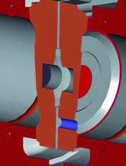
- Drilling through one wedge disc, connecting the central part with the inlet end. This is the simplest solution. For use as a unidirectional valve only. The flow direction must be marked.
- Connecting the bypass to the central part – a relatively simple and effective solution. Used for all bypasses consisting of at least two valves, between which the connection is located. This applies to all gate valves of DN 200 and larger. Depending on the flow, one valve must always be open.
- Relief valve located at the end of a pipe led out of the gate valve chamber. Although it is the most expensive, it is a fully universal solution applicable to all gate valves and all operating parameters. The relief pressure setting must be specified in the order.
Hotline
Do you need advice on choosing a valve, want to order spare parts or need a service visit? Call or write to us – our engineers and sales staff will be happy to help and propose the most suitable solution.